Schematic Reference

Main Menu
When in schematic view, the following menu bar is displayed.

If you do not have a design open, only the File, View, PCB123, and Help menu items are available.
File menu
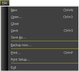
New
The File > New command is one method of creating a new PCB design. It will invoke the Board Configuration Dialog to allow you to set board parameters or load a netlist unless you have checked the Do Not Show button in the Board Configuration dialog in which case a blank design is created.
Open…
The File > Open command invokes a standard Windows file dialog that allows you to browse to and select one or more PCB123 design files. You can select multiple designs to open by holding down the Shift or Ctrl key while clicking on files. If you select multiple design files, each one will be opened in its own window.
Close
The File > Close command closes the currently active design. If the design has been modified, you will first be prompted to save your changes.
Save
The File > Save command writes a copy of the currently active design to disk using the same filename the design was opened with. If it is a new design that hasn’t been previously saved, then you will be prompted for a filename to save as (see below).
Save As…
The File > Save As command prompts you for a filename using the standard Window file dialog. This will write a copy of the currently active design to disk under the name supplied. If the file exists, you will be prompted to overwrite the existing file.
The entire state of your design is saved to disk with the exception of DRC markers and the local footprint cache. All display settings are saved in the file so the next time the file is opened it will appear the same as when it was saved.
Backup Now
The File > Backup Now command initiates an immediate backup of the currently active design.
Normally, in the course of design, PCB123 automatically saves a backup of all open designs once every ten minutes. It saves them to the Backup subdirectory using the name of the design and appending “_BACKUPn” where n is from 1 to 5, 1 being the most recent backup.
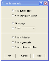
The File > Print command invokes a schematic print dialog box.
From the Schematic print command, you can print the current page or all schematic pages in your design. You can specify who to fit or scale your output, and you can specify color printing options.
Print Setup
The File > Print Setup command invokes the standard Windows print setup dialog and is used to set print defaults for the above print command.
Exit
The File > Exit command exits the PCB123 program. You will be prompted to save any modified documents that you may have open.
Edit menu
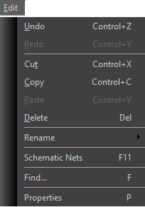
Undo
The Edit > Undo command undoes the last change to currently active design. Virtually all changes to the design are recorded and can be undone in reverse order. There is no limit to the size of the undo buffer other than memory limitations.
What constitutes a change for purposes of undo is operation dependent. In many cases an entire group of changes will be undone with a single undo command. For instance, selecting undo after an autoroute will undo the entire autoroute results, not just the last connection the autorouter completed.
When a change is undone, that change will be added to the Redo buffer in case you change your mind and want to redo it again. See below.
Redo
The Edit > Redo command redoes the last undo operation. Repeated undo operations are stored to the redo buffer so you can redo a whole series of undo operations.
Cut
The Edit > Cut command deletes the currently selected set of objects and places them into the paste buffer. There is only one paste buffer so only the last cut operation is available for paste.
See the Paste command for more information.
Copy
The Edit > Copy command copies the currently selected set of objects into the paste buffer. There is only one paste buffer so only the last copy operation is available for paste.
See the Paste command below for more information.
Paste
The Edit > Paste command makes a copy of the objects in the paste buffer and inserts them into the currently active design.
First, any components in the paste buffer are added to the design by assigning them a new reference designator that does not conflict with one already in the design. Their alpha-prefix is retained.
Next, any complete routes or connections that start and end at pins that are also in the paste buffer will be added to the design. They will retail their original net name with a unique numerical suffix.
Lastly, all text and non-net-attributed board outlines will be copied without change. Net-attributed board outlines will either inherit a cloned net name or retain their original net names depending on whether their original net names were cloned during the paste operation.
After all objects are created, they will be in a selected state attached to the cursor ready to be placed.
Delete
The Edit > Delete command deletes all selected objects from the currently active design.
The delete operation can later be undone.
Properties
The Edit > Properties command is context sensitive. If you have nothing selected it invokes the Board Configuration Dialog. If you have one or more objects selected, then you will get a property page for each class of object selected.
See Object Property Pages for more information.
Insert menu
Top-level Insert menu
|
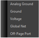
Insert Port submenu
|
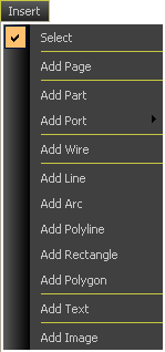
Add Page
The Insert > Add Page command inserts a new, blank schematic page for use in your design.
Often, designers will find it helpful to break the schematic into multiple pages organized by function. The network connections between these pages are accomplished using port connectors. The entire schematic network is then made available to the layout page for physical design.
Add Part
The Insert > Add Part command displays the Select Part dialog box, allowing you to search for, preview and select the part you need from the schematic parts taxonomy.
Add Analog Ground Port
The Insert > Add Port > Analog Ground command provides you quick and easy access to a predefined analog ground symbol.
By selecting the Analog Ground Port, your cursor moves into parts placement mode with an analog ground pin ready to be placed.
Add Digital Ground Port
The Insert > Add Port > Ground command provides you quick and easy access to a predefined digital ground symbol.
By selecting the Digital Ground Port, your cursor moves into parts placement mode with a digital ground pin ready to be placed.
Add Voltage Port
The Insert > Add Port > Voltage command provides you quick and easy access to a predefined voltage port symbol.
By selecting the Voltage Port, your cursor moves into parts placement mode with a voltage port ready to be placed.
Add Global Net
The Insert > Add Port > Global Net command provides you quick and easy access to a predefined global net symbol.
By selecting the Global Net, your cursor moves into parts placement mode with a voltage port ready to be placed.
Global nets serve to connect to the net with the same net name across the entire set of schematic pages.
Add Off-Page Port
The Insert > Add Port > Off-page Port command provides you quick and easy access to a predefined off page port symbol.
By selecting the Off-page Port, your cursor moves into parts placement mode with an off-page connector ready to be placed.
Off-Page connectors are similar in function to global nets.
Add Line
The Insert > Add Line command allows you to add line objects to the currently active design schematic by first defining one endpoint, then the other.
Add Arc
The Insert > Add Arc command allows you to add arc objects to the currently active design or footprint by first defining one endpoint, then the other, and then adjusting the radius.
Arcs have definite width and are always chords of a perfect circle. They cannot be elliptical.
Add Polyline
The Insert > Add Polyline command allows you to add a poly-line object to the currently active design.
A polyline is a continuous series of line segments. They have a physical width and may be net attributed. In most cases polylines are not net attributed as they are widely used for nomenclature such as component outlines and title blocks.
Once you enter Add Polyline mode, a series of straight line segments will be connected between each successive left-mouse click. Double click on the last point to terminate the polyline definition process.
Add Rectangle
The Insert > Add Rectangle command allows you to begin digitizing corners of rectangular board outlines.
As you add a rectangle, you will be prompted to digitize two opposite corner points. The rectangle will determine its width and length from these two points.
Add Polygon
The Insert >Add Polygon command allows you to begin digitizing corners of polygon and polylines.
A polyline is a continuous series of line segments. They have a physical width and may be net attributed. In most cases polylines are not net attributed as they are widely used for nomenclature such as component outlines and title blocks.
A polygon is a closed 2-D surface. They do not have width. What you draw is the absolute edge of the board outline. They can be convex or concave but should not self-intersect.
See the Board outline Context Pane and the Board outline Property Page for more information.
Add Text
The Insert > Add Text command allows you to add rendered text “strings” to the currently active design or footprint. When you first select this command you will be prompted for the string to add with the Add Text Dialog.
Currently, only the ANSI character set is supported. Extended ASCII characters are not rendered but are stored in the string.
There is only one font available for text strings because the characters must be stroked and there is no reliable way to convert a TrueType font into a series of strokes that can be added to the board. This may change in the future.
Add Image
You can add an image for any reason necessary to clarify your project, or if you want to change the logo in the title block. This is done in the schematic page.
View menu
Top-level View Menu
|
View/Toolbars Submenu
|
View/Zoom Submenu
|
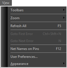
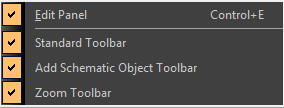

View Standard Toolbar
The Toolbars > Standard Toolbar command toggles the visibility of the Standard Toolbar.
View Add Object Toolbar
The Toolbars > Add Object Toolbar command toggles the visibility of the Add Object Toolbar.
View Zoom Toolbar
The Toolbars > Zoom Toolbar command toggles the visibility of the Zoom Toolbar.
Zoom Submenu
The Toolbars > Zoom Toolbar command toggles the visibility of the Zoom Toolbar.
Zoom In
The Zoom > Zoom In command increases the magnification of the display. If this command was invoked through the menu then the view center remains unchanged. If this command was invoked with the PgUp key then the view center will be where the cursor was when the command was invoked.
Zoom Out
The Zoom > Zoom Out command decreases the magnification of the display. If this command was invoked through the menu then the view center remains unchanged. If this command was invoked with the PgDn key then the view center will be where the cursor was when the command was invoked.
Zoom All
The Zoom > Zoom All command sets the screen magnification such that all objects fit on, and are centered on the screen.
Pan Up
The Zoom > Pan Up command moves the view center up nearly one full screen height.
Pan Left
The Zoom > Pan Left command moves the view center to the left nearly one full screen width.
Pan Right
The Zoom > Pan Right command moves the view center to the right nearly one full screen width.
Pan Down
The Zoom > Pan Down command moves the view center down nearly one full screen height.
Redraw
The Zoom > Redraw command repaints the screen.
Tools menu
Top-level ToolsMenu
|
Tools/Netlist Submenu
|
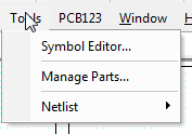
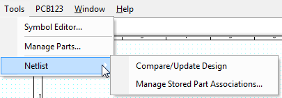
Symbol Editor…
The Tools > Symbol Editor… command will present the user with the Symbol Editor dialog box, ready to create a new symbol from scratch. The function of the symbol editor is discussed elsewhere in this manual.
Manage Parts…
The Tools > Manage Parts… command will present the user with the Define Part dialog box. From here, the user can create parts, review or edit the contents of parts, and delete parts as needed.
Generate Netlist from Schematic…
The Tools > Generate Netlist from Schematic command will create a netlist file of your schematics’ electrical network. The user will be presented with a Windows standard file save dialog box, allowing the user to specify the location for the netlist file to be output.
PCB123 menu
Top Level PCB123 menu
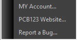
MY Account…
The PCB123 > My Account command will invoke a browser session to your account status page at Sunstone.com. Once you’ve logged in, you can view your personal account settings including: your default user preferences (shipping address, carrier, payment method, etc.); personal profile information (name, company, email, etc.); and recent order activity including current status for any orders in process.
PCB123 Website…
The PCB123 > PCB123 Website command will invoke a browser session at www.sunstone.com
Report a Bug…
The PCB123 > Report a Bug command will invoke a browser session and take you to the Contact Us page for technical support on the www.sunstone.com website. From here you can report the bug details. Customer Service will acknowledge receipt of your bug report, and follow up with you as necessary.
Window menu

Cascade
The Window > Cascade command will rearrange open design windows into a cascading pattern.
Tile Horizontally
The Window > Tile Horizontally command will rearrange open design windows into a horizontal tiled pattern.
Tile Vertically
The Window > Tile Vertically command will rearrange open design windows into a vertical tiled pattern.
Arrange Icons
The Window > Arrange Icons command will move any iconized design files into an orderly row across the bottom of the PCB123 editing pane background.